Hello, welcome to HuanTuoTechnology
Collection | Message | 中文

Hello, welcome to HuanTuoTechnology
Collection | Message | 中文
mailbox:herry@vivjack.com
Telephone:86-769-87388642-128
Fax:86-769-873888652
address:No. 88 Liangtouwei Street, Liheng Management Zone, Qingxi Town, Dongguan City, Guangdong Province
 |
 |
 |
 |
 |
 |
 |
 |
 |
 |
With the continuous development of electronic technology, electrical connectors are applied more and more widely. The main function of electrical connectors is to realize signal transmission and power transmission between devices. In order to ensure the stability and reliability of electrical connectors, people have been discussing and studying the reliability of electrical connectors'contact socket. The reliability of the end connection of the connector contacts is neglected. In recent years, in dealing with the quality problems of the whole system, it has been found that poor contact and unstable transmission signal are sometimes the faults caused by poor contact of connector cables, mainly manifested by welding virtual welding, wire dropping, etc. Therefore, to ensure the reliability of connectors in the whole system, not only the inherent reliability of products, but also the reliability of products.
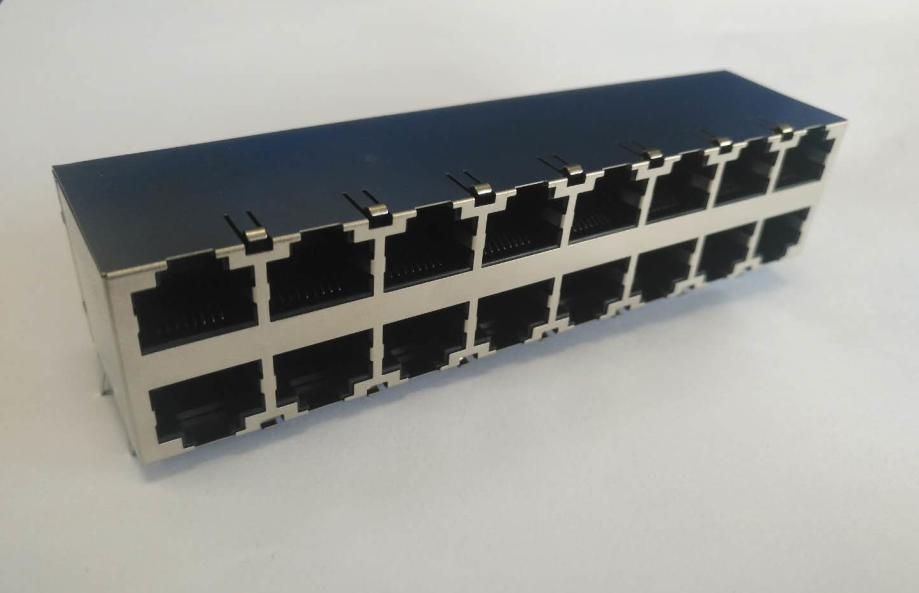
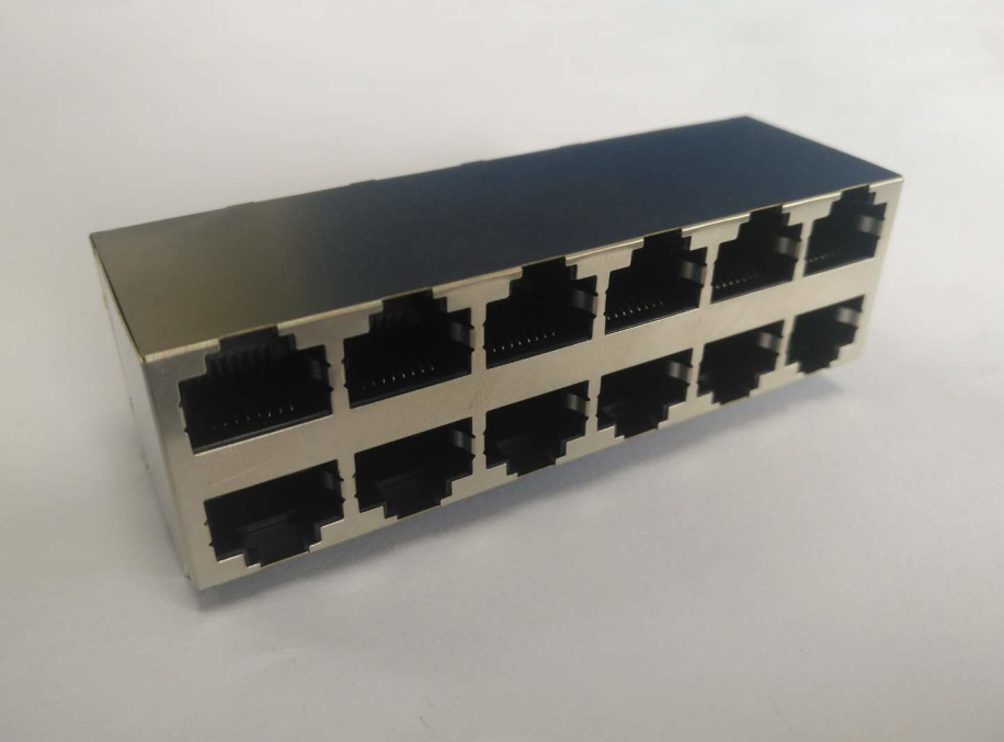
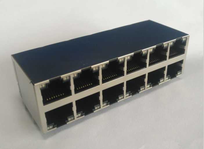
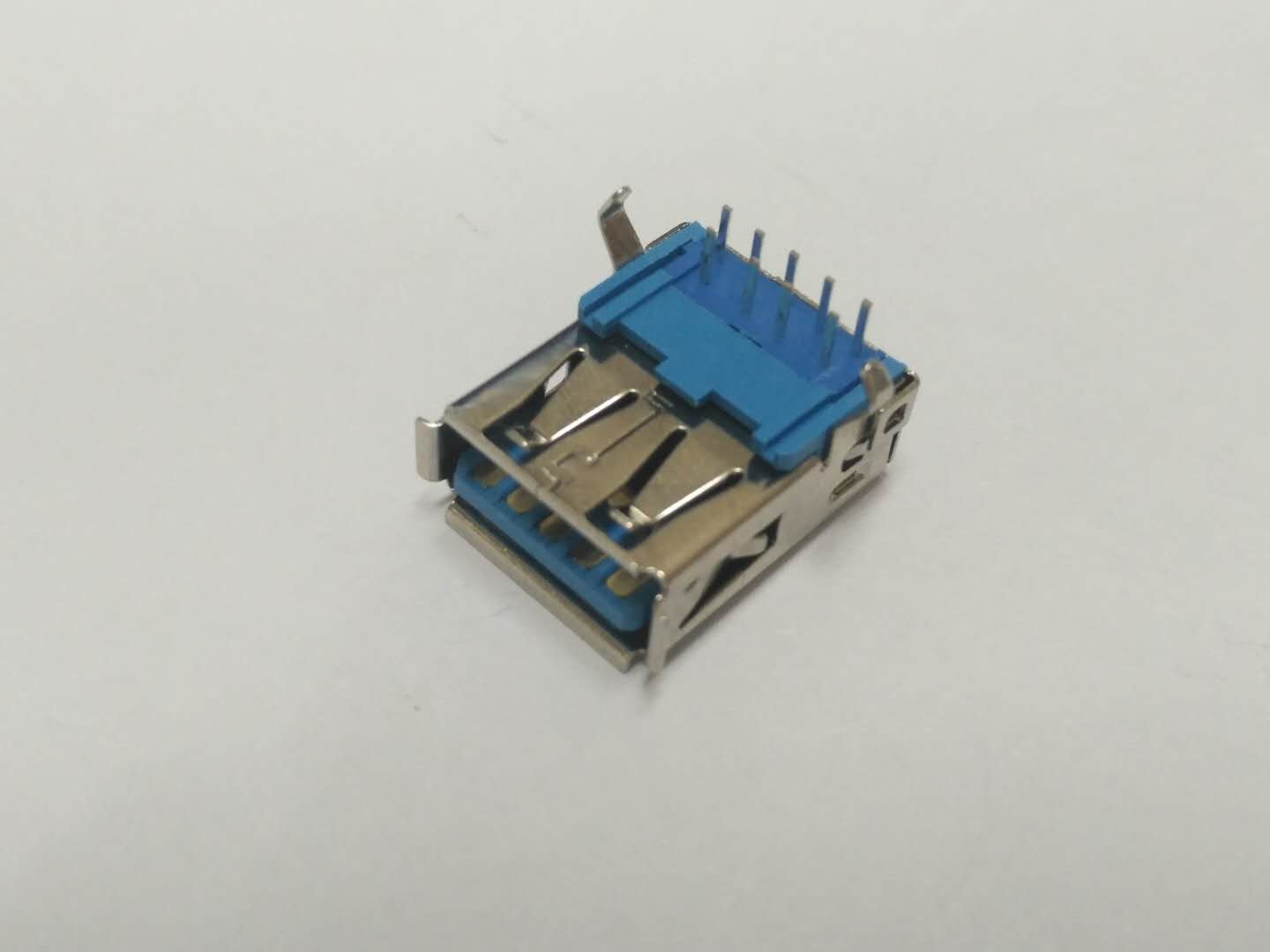
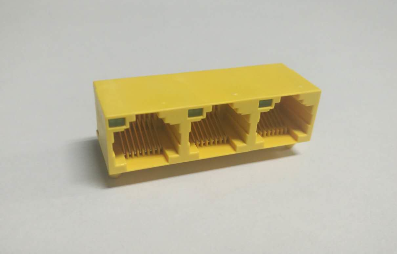
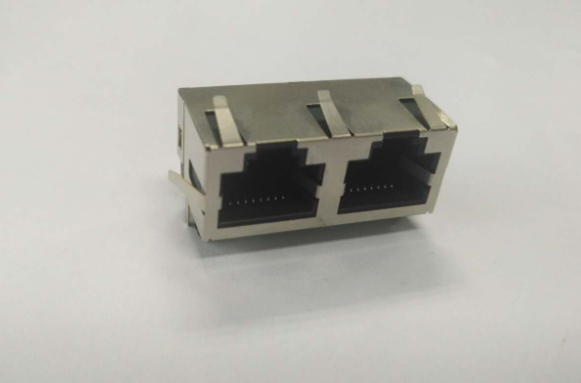
Contact end form
In connectors, contacts are an important part of connectors, which mainly undertake the transmission of signals. In the connector design, the contact part is composed of two parts: the plug end and the tail end. The socket end is generally composed of elastic parts and rigid parts to ensure the reliability of the contact between the connector plug and socket; the end of the contact part is to realize the cable connection between the devices, the interconnection between printed boards or the interconnection between cables and boards, which is used for cable connection. The end of the connector is in the form of welded wire and pressed wire. Insulation skin puncture type (IDC, non-welded winding type), used for printed circuit boards, contact parts end-connected form of direct welding, bending welding, surface sticking and non-welded indentation type.
2. Design Requirements for Contact End
For electrical connectors, electrical connector contacts can be divided into two types, one is the standard type, that is, the contact structure, terminal mode and line specifications are clearly in accordance with the requirements, users can see the product instructions when using. Table 1 lists the wiring range of common contacts (Table 1).
The other is non-standard contact parts, which are designed according to the cable requirements of the whole machine. Firstly, the size of the plug-in end, the installation form of the product, the appearance mode and the cable specifications are determined. When the cable is uncertain, the design principle is to design the connection holes according to the contact number, which should meet the requirements of the maximum wire gauge number conductor. The ratio of the diameter of the conductor core to the diameter of the solder cup is generally 0.5-0.7. When connecting a conductor, the design principle is that the diameter of the cable core should match the diameter of the connection holes of the contact parts. The ratio of the diameter of the core wire to the inner diameter of the welding hole is generally 0.6-0.8.
3. Requirements for Use
In the assembly process of electronic circuit, welding technology is an important link. In order to ensure the reliability of the connection, the following points should be paid attention to:
1) Common standards for electronic assembly:
IPC J-STD-OOO1F CN-2014 welding requirements for electrical and electronic components should strictly implement the welding standards;
GB/T 3131 Sn-Pb solder requirements and test methods;
GJB 5020-2001 Pressure Joint Technical Requirements.
2) When welding a cable, no more than three wires should be inserted in one welding cup, multiple cores should be kept neat and not broken, and all of them should be inserted into the bottom of the welding cup. The weld seam is formed along the contact. The solder should wet the whole inside of the welding cup and fill at least 75% of the cup mouth.
3) Choose the welding tube type (mainly used in the inner conductor of coaxial cable), choose the appropriate welding fixture when welding, and place the solder on the welding fixture. Before welding, the welding position of inner conductor must be positioned well to ensure that the dimension of inner conductor after welding meets the requirements of drawings. When welding, proper flux (rosin flux) should be uniformly coated on the welding part at first, and tin-enameling treatment should be carried out on the wire and welding hole. A suitable amount of tin wire should be dipped in 60W electric soldering iron to contact the welding part of the inner conductor. Cable should be pulled during welding, heating time is 3-5 seconds, and the electric soldering iron should be removed finally through observation. Hole inspection of welding quality requires that the solder should not be higher than the observation hole and that there is no solder in the observation hole.
4) When two wires are welded in one welding cup, the sum of the diameter of the core wire shall not exceed 90% of the diameter of the inner hole of the welding cup. When welding three wires, the diameter of the outer tangential circle of the cross-sectional area of the conductor core is prohibited to exceed 90% of the diameter of the welding cup.
5) No welding without inserting wire core into the bottom of the welding cup: manual welding, no forced cooling of solder joints.

Dongguan Xingte Electronics Co., Ltd. technology:shangke
Telephone:86-769-87388642-128 Fax:86-769-873888652
address:88 Liangtouwei Street, Liheng Management Area, Qingxi Town, Dongguan City